Kubo: Safety System
- Create Connector Wiring Diagram
- Add Resistor to Wiring Diagram
The original B7510 platform on which Kubo is built has built-in systems to ensure that the driver never activates or operates the vehicle in an unsafe state. This system consists of a set of safety switches that sense the state of the vehicle, relays that control the electrical transfer from the battery to various components that start or run the tractor, and an integrated circuit known as the Operator Presence Controller (OPC). For more information, please consult the B7510 Workshop Manual (NOT the Operator's Manual).
The following image shows the schematic for the OPC circuit from the aforementioned manual:

Kubo is a B7510DTN, which stands for Dual Tractor 4wd, Narrow Specialty Tractor (source). As such, in the diagram above, there is no Mid PTO Switch (10) due to the lack of bucket attachment capability.
Switches
- Rear PTO Switch: The Power Take-Off switch on the left hand side of the seat is connected - ensures that the Power Take-Off does not start spinning when the tractor starts.
- Seat Switch 1: Seat Switch 1 underneath the seat is connected - ensures that the operator is sitting the seat when the tractor starts.
- Note: this switch has been bypassed with a jumper so that the tractor will start without an operator in the seat.
- Seat Switch 2: Seat Switch 2 underneath the front lip of the seat is disconnected - ensures that the seat is not tipped forward when the tractor starts.
- HST Pedal Switch: Hydrostatic Transmission Pedal Switch near the velocity pedal is connected - ensures that the pedal is in the neutral position when the tractor starts.
- !!! Clutch Pedal Switch: Clutch Pedal Switch underneath left side of the tractor is connected - ensures that the clutch pedal is pressed when starting the tractor.
- Note: this switch is on the output of the OPC rather than the input, which means that the OPC can output a "start" signal, but if the clutch is not depressed, the Engine Stop Solenoid will allow the engine to start, but the Starter will not receive power to start the tractor.
Controls
- Key Stop Relay (KSR): KSR connects battery power to the Engine Stop Solenoid when it is activated by the OPC.
- Starter: Starter turns over the engine the first few times to get the enginer started when it is provided power by the OPC.
- Note: the Clutch Pedal Switch must be depressed
The following image shows the location of the OPC and Key Stop Relay (KSR):

The original tractor Emergency Stop System documentation from the 2014 team consisted of a single email sent to the team from one of the prior scope members, Ken Berry, which read as follows:
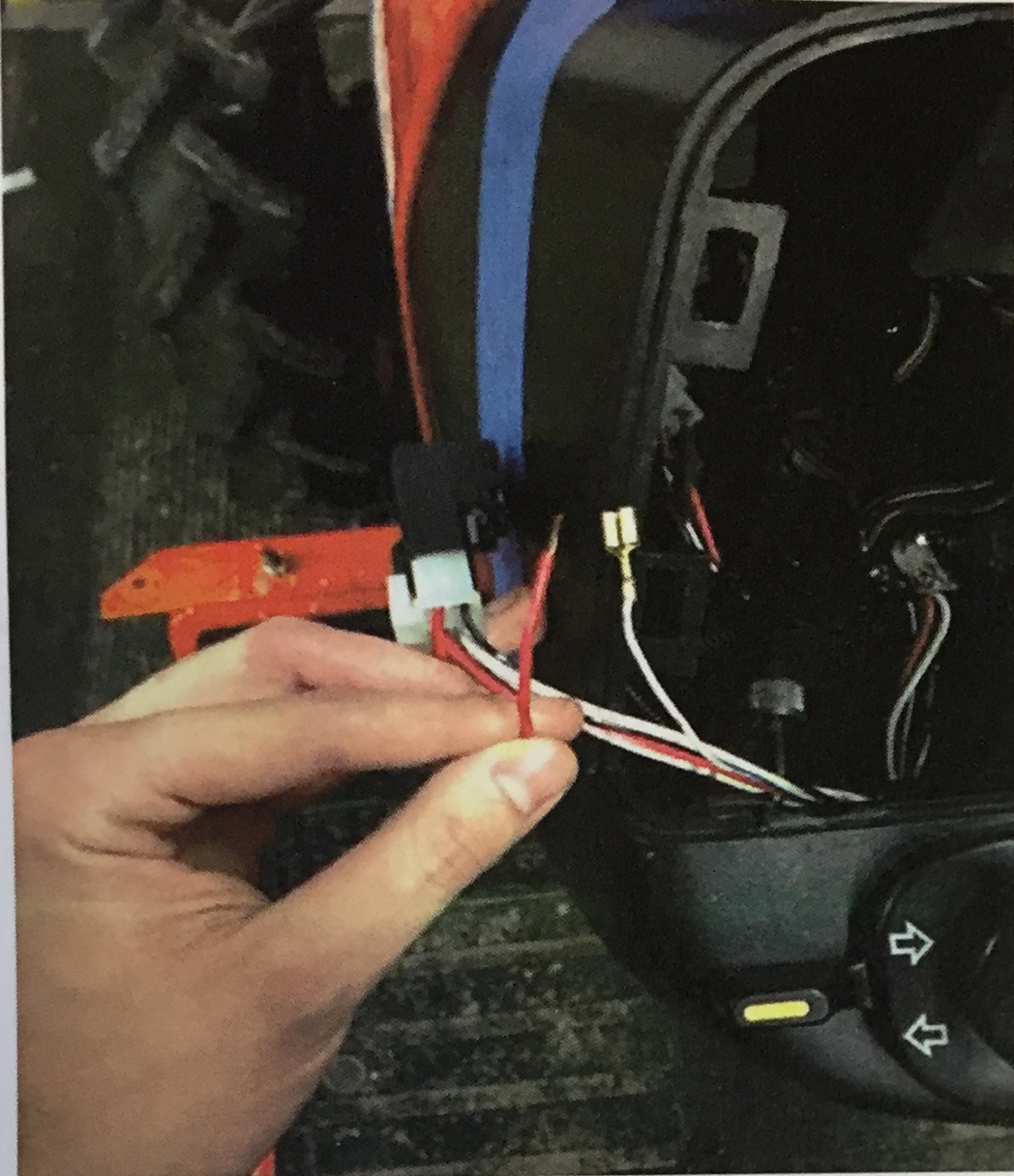
I added a jumper in the wiring in the dash for you to hook up the E-stops. Currently there are two wires disconnected: a white-and-blue one coming from the wiring harness (with a spade connector on the end) and a red one coming out of the black key-stop relay (see picture below). When you turn the key to "RUN", the blue-and-white wire energizes that relay which in turn energizes the fuel shutoff solenoid. If you break the connection between that wire and the relay, the fuel shutoff solenoid closes and shuts off the engine. I removed the blue-and-white wire from the plug (that plugs into the relay) and put that red wire in where it was. If you wire your e-stops in series between the blue-and-white wire and the red wire, pushing any of the e-stops will kill the engine immediately. Additionally, it will prevent the engine from starting if one of the e-stops is engaged. That wire only supplies like .13A at 12V with the key on (I tested it), so it should work well with the small gauge wire y'all are using for your estops. My only request is that you not cut the blue-and-white wire. I want to avoid cutting the stock wiring harness as much as possible, which is why I set this up the way I did.
The following image accompanied the email:
The blue-and-white wire referred to by Ken Berry is the signal output from the OPC - severing this connection with the E-Stop buttons would prevent signals from the OPC from reaching the KSR. Experiments from Fall 2019 in preparation for editing the circuit found that as resistance was added to the line in question, the voltage held across the line dropped, warning of too much load on the line. When a relay was added in an effort to shut off the motor power with the estops, the coil resistance added to the line broke the OPC (Operator Presence Controller). System V2 was designed and implemented in Spring 2020 to fix this problem.
Kubo has multiple Emergency Stop (EStop) buttons placed in accessible locations throughout the vehicle. all of these buttons are latching switches that break a circuit when pressed, and are all connected in series. This circuit is intended to perform two functions when an EStop is pressed:
- Stop tractor engine
- Cut motor power
An appropriate circuit design would perform these two functions while optimizing two additional constraints:
- Draw a minimal amount of additional current
- Maintain a factor of safety such that the tractor starts across a wide range of battery voltages
Experiments and calculations were performed to design this circuit: Safety System Electrical Experiments. The results from this work demonstrated three conclusions:
- The relays must be installed in parallel to ensure that sufficient current is supplied for switching.
- When the relays are installed in parallel, a sufficient margin of resistance exists to account for the resistance of the estop wiring circuit.
- The minimal resistance of the estop wiring circuit requires an additional 10 Ohm resistor to be installed to follow Constraint 1.
The following image shows additional proposed wiring in black, and current wiring in grey. The new hardware shown below is listed on the wiki page Kubo: Hardware:

| Image | Hardware | Links | Count |
|---|---|---|---|
|
|
BACO Mushroom Head Stay-put Estop | (reference) | 4x |
 |
12 VDC 30-40A Automotive Relay | (reference) | 2x |
 |
Philmore Relay Socket | (reference) | 2x |
 |
Bussmann Inline Fuse Holder | (reference) | 1x |