-
Notifications
You must be signed in to change notification settings - Fork 10
PMS5003 PM
The Rigacci blog post for setting up the PMS5003 was not enough to get the sensor running, so for this sensor i will be explaining the steps i did to get it running. This includes both the hardware and software portion of the sensor.
To connect the sensor to the breadboard, I needed to modify the cable as i was not able to find an adapter for this specific female connector.
I contacted the blog writer on how he connected the sensor, but unfortunately, the author did not find a suitable male connector to solder to the PCB. Instead, on the PCB he used a 4x2 standard header pins (2.54mm step), albeit one annoying part was to cut the PMS5003 wire at one end, and to solder wires with Dupont standard female connector.
Following his advice, I went ahead and spliced one end of the wire to a jumper wire, although if i were to do this again i would have crimped the end to a female header instead as i could have directly plug the header to the gpio pins.
After splicing, i tinned the wires with solder to strengthen the connection and finished it off with heat shrink tubing. I followed this tutorial on splicing wire. The finished cable would like this.
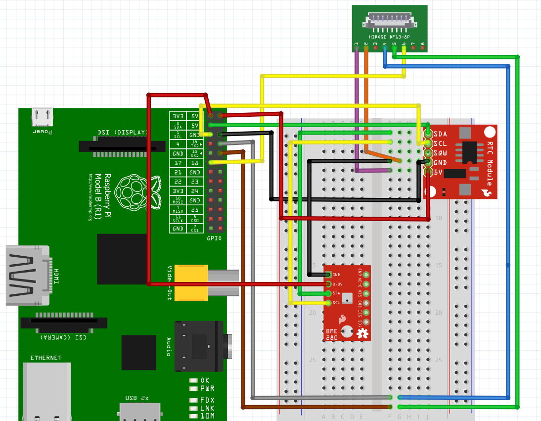
Now that we have a cable that can be connected to the breadboard, refer to these two pictures below to on how to connect the sensor to the raspberry pi. One is for the sensor pin to raspberry pi and the other is for pin numbering.
Here is the wiring diagram for the PMS5003, please note that it is represented by the hirose ds13-8p connector as i was unable to find the part library for the sensor. The pin numbering is the same as in the pin numbering diagram above. Please note that pins 3,7, and 8 have been purposely left unconnected.
Unlike the other sensors that we have been using, the PMS5003 communicates via serial line rather than i2c. The communication protocol for this sensor is a 32 byte frame, which means that each "message" the sensor sends is 32 bytes long. To see what each byte of the frame represents refer to pages 13 - 14 of the transport protocol-Active mode table. Keep in mind that each byte is represented as an 8 bit binary data as this will be useful for understanding how to parse the data in a bit.
In serial communication, there are protocols built-in so that we can check the validity of the data we receive. These mechanisms are there because data transfer is not always perfect due to various reasons. With this in mind, in each frame along with data bytes there are special bytes that we can use to check if the frame we received has error. Following the transport protocol table in the datasheet, we are given the ability to check for the following:
- start/flag bytes - each frame begins with 0x42 (ascii 'B') followed by 0x4d (ascii 'M')
- frame length - compare the length of the frame received to the frame length byte
- checksum - the sum of the frame values is equal to this check byte
However i found that checking for the frame length would not be as useful as compared to checking the checksum as that is a much more powerful method of checking for error in the data. This is because the checksum byte is accounting for each byte value and we will know if there is an error in the byte received.
Resource to better understand framing in serial communication
The resulting data from the serial line is in binary format where each data block is represented by two 8 bit binary (i.e. there is data 1 high 8 bits and data 1 low 8 bits). To parse this into a data type that is usable, we can use the unpack() method from the struct library which will do the conversion from two unsigned 8 bit integer into a unsigned 16 bit integer. The formula to convert is
data_16bit = (data_high_8bit)*256 + (data_low_8bit)
The format string is >HHHHHHHHHHHHHH was taken from the adafruit's circuipython example code.
The > represents big-endian byte order. When data is read from the serial line, the 8 bit pair are always given in the order of high and then low. For example, data 1 high is read first and data 1 low follows after.
The H represents a conversion from unsigned short to an integer and the amount of 'H' should match the number of data were unpacking (we are unpacking data 1 - data 14 and therefore should have 14 'H')
We can always check if the unpacking method is doing the proper conversion by manually doing conversion ourselves.
Here is a visual guide of how the data is read from the serial line and then converted to a single 16 bit integer data value.
The parsed data will give us the following:
- PM1.0, PM2.5, PM10.0 concentration (ug/m^3) standard units
- PM1.0, PM2.5, PM10.0 concentration (ug/m^3) environmental units
- Number of particles of sizes 0.3um, 0.5um, 1.0um, 2.5um, 5.0um and 10um per 0.1L of air
I could not find proper documentation on the difference between standard and environmental units, however i tried running the sensor and directly compared the value being outputted and did not find a difference in the values i was getting.
- Maximum Consistency Error: ±10% @ 100~500 μg/m³ (pg.3)
