-
Notifications
You must be signed in to change notification settings - Fork 9
2018‐02 System Requirements
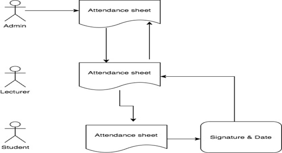
The current system of class attendance is manual. The administrative officer print a sheet, the sheets are distributed in the classrooms. The lecturer takes the sheet during each class and passes it around for the students to fill it in and sign it. The process is shown in Figure 5.

Figure 5: The functionality of the existing system
Based on the current system, the requirements were identified and recorded in the user stories. These included identifying validation rules, constraints and business rules. All the requirements were documented as user stories in the online Microsoft visual Studio.
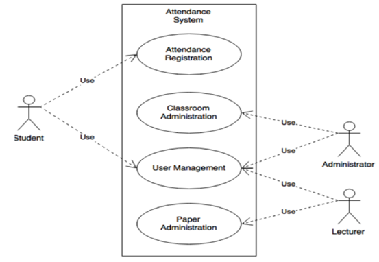
To be able to effectively describe the set of actions that need to be performed by the automated system, the Use case diagrams were created using draw.io. This helped in describing the set of actions that the system should perform in collaboration with the external users of the system. Figure 6 represents the first cut of the problem domain.

Figure 6: The first cut of the problem domain
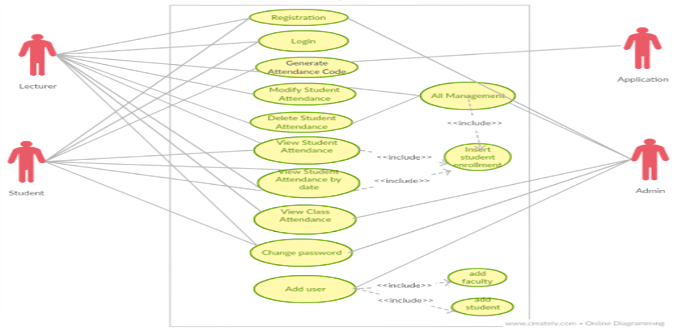
The proposed functionality of the system is represented using the use case model. It helped to capture the problem domain in terms of functionality to be provided. It helped to identify the flow of events. It helped address questions like:
- Who are the users of the functionality?
- What kind of hardware is needed to accomplish this functionality?
- What software implementations are needed?
- Are there any external systems that the proposed system needs to interact with?
- How do the entities identified interact internally?
 Figure 7: Use case model for the proposed system
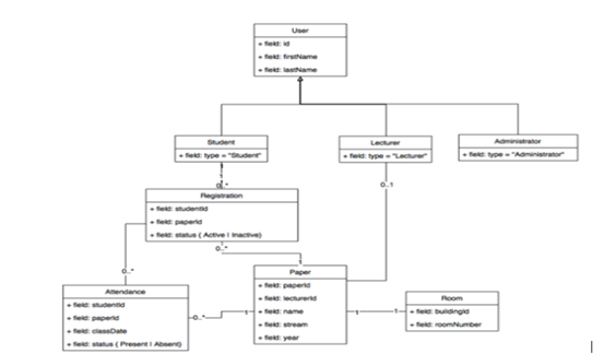
To illustrate the relationships and dependencies that exist among the different classes identified in the system, the class diagram was created. In this context, Figure 8 defines the different methods and variables associated with an object.

Figure 8: Class Diagram representing the business context
Back | Next