OK, so the new and shiny SD2IEC wasn't all you wanted from a lowcost floppy emulation solution for your Commodore 64! Sure, there are other good solutions out there for those willing and able to put a lot of money into the FPGA-based alternatives - personally can see myself affording one of them someday, but that needs saving up some money I don't currently have. Also, I don't want my other retro computers to think I'm completely biased towards the Commodore-stuff so options were needed...
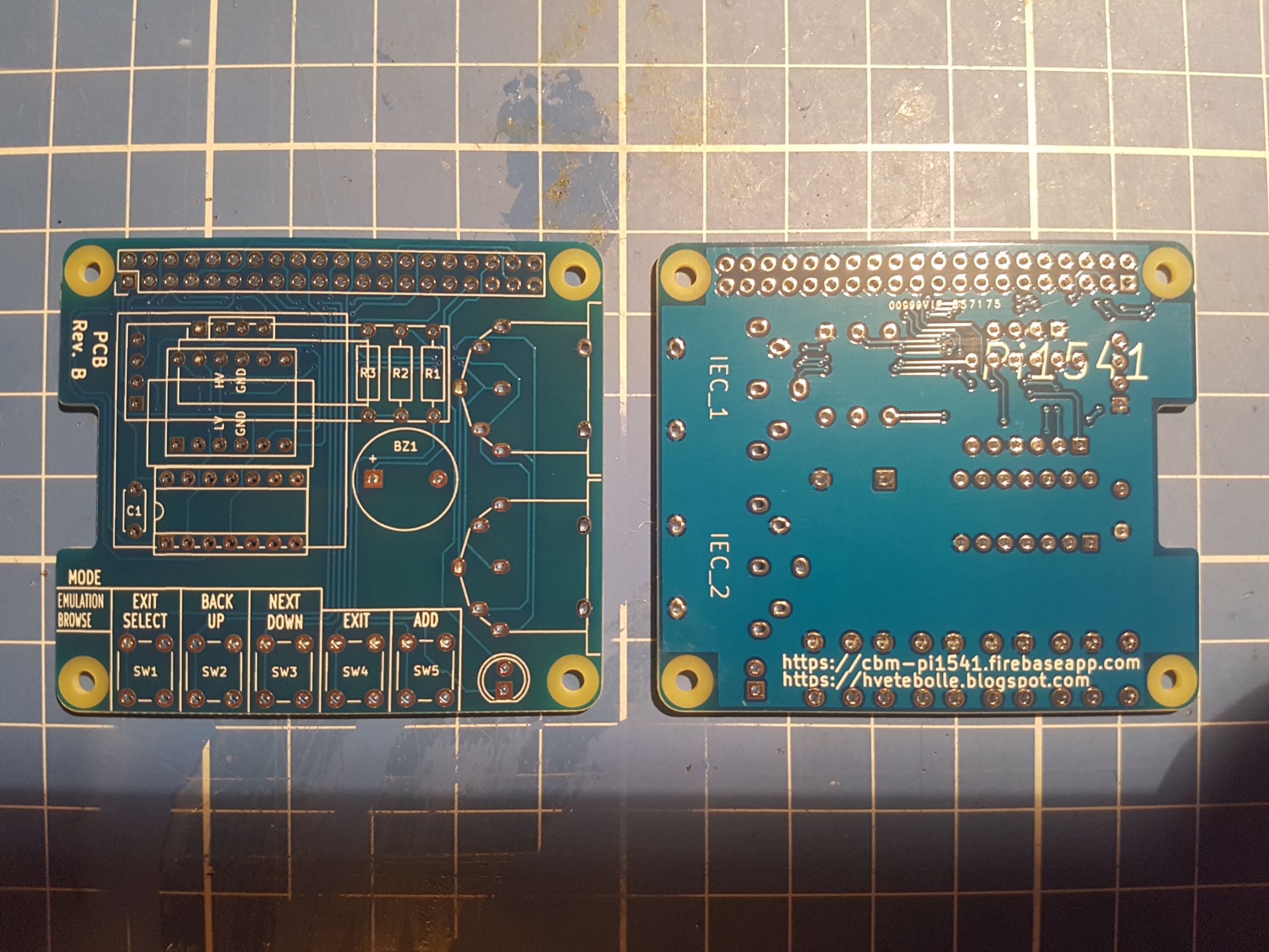
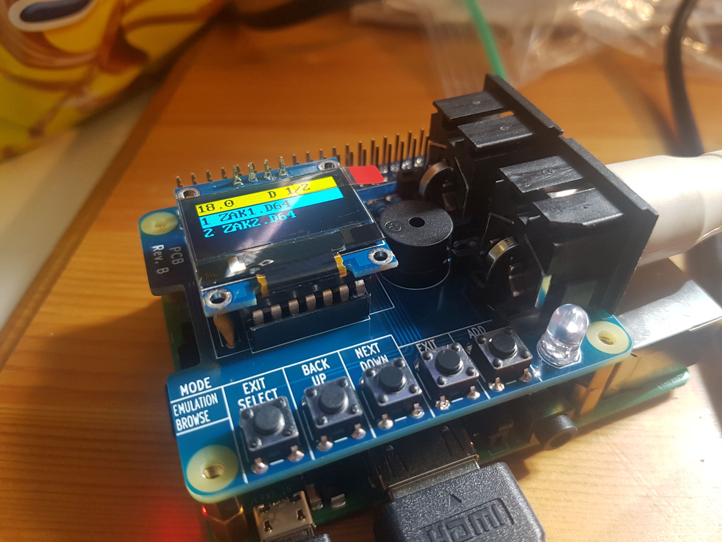
Thankfully, some enterprising folks have taken it upon themselves to create a solution based on the Raspberry Pi (3B or newer) and with some extra modifications we all can build one. Personally I prefer clean and nice PCBs over hacked together stuff, so away I went to make one in KiCAD. My design is based on what the original coder of the Pi1541 software has named option B, but given that option A assumes only one device on the serial bus I wanted something that would work with a physical 1541 drive as well (how else am I supposed to backup my old rotting disks?).
For more details on the software, see https://cbm-pi1541.firebaseapp.com/ for more details not included in my humble hobby project. The base template used as a starting point for the RPi hat, including RPi-specific connectors, is found on https://github.com/xesscorp/RPi_Hat_Template.
This is the part list as it stands now, everything should be readily available from your friendly neighbourhood electronics store - for me that means ebay, but your mileage may wary. The design of the board has been kept simple so that anyone with access to a reasonably sized soldering iron should easily be able to assemble it themselves, all parts are through-hole so no need to fear those tiny SMD-parts because you won't find any of them here!
Values in parenthesis are components that are to be considered optional, but if you want to build it for yourself I higly recommend them as they only slightly increases the overall cost of doing this project. Displays should be of the I2C-variety with 4 pins in the following order: GND, VCC, SCL and SDA.
| Reference | Item | Count |
|---|---|---|
| PCB | Fabricate using Gerber files (order) | 1 |
| J1 | 2x20 pin long female header | 1 |
| BZ1 | Buzzer (7mm pin spacing, 5mm OK) | (1) |
| C1 | 100nF ceramic capacitor | 1 |
| R1 | 100 Ohm resistor | 1 |
| R2, R3 | 1k Ohm resistor | 2 |
| IEC1, IEC2 | Female S-terminal 6pin DIN PCB | 1 (1) |
| IC1 | SSD1306 OLED-display 128x64 (0.96") | (1) |
| IC2 | 7406 DIP | 1 |
| IC3 | 4ch I2C level converter module | 1 |
| IC4 | SSD1306 OLED-display 128x32 (0.91") | (1) |
| SW1-SW5 | Momentary push button, 6x6mm | (5) |
| D1 | 5mm LED, red for authenticity | 1 |
Please use the order link above when signing up to help me support this project, I'll get a small discount on future orders and hopefully that means I can afford to keep developing new and exciting modules in the future. By using the URL you won't have to deal with the rather daunting order forms for PCB fabrication, but if you want to go that route they'll probably want a zipped-up copy of the files in the export-directory!

