This repository has been archived by the owner on Jul 18, 2024. It is now read-only.
forked from Ladvien/HM-10
-
Notifications
You must be signed in to change notification settings - Fork 14
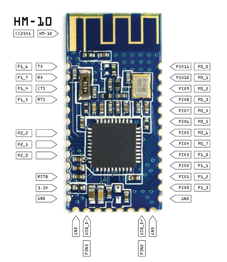
HM 10 Pinout
Nick Walker edited this page Aug 9, 2014
·
9 revisions

| No | Name | Description | CC2541 Pin Name (Description) |
|---|---|---|---|
| 1 | UART_TX | UART Interface | P1_6 |
| 2 | UART_RX | UART Interface | P1_7 |
| 3 | UART_CTS | UART Interface | P1_4 |
| 4 | UART_RTS | UART Interface | P1_5 |
| 5 | NC | No connection | |
| 6 | NC | No connection | |
| 7 | NC | No connection | P2_2 (Debug clock) |
| 8 | NC | No connection | P2_1 (Debug data) |
| 9 | NC | No connection | P2_0 |
| 10 | NC | No connection | |
| 11 | RESETB | Reset if low longer than 100ms | RESET_N |
| 12 | VCC | 3.3v | |
| 13 | GND | Ground | |
| 14 | GND | Ground | |
| 15 | SCL | I2C Interface | 2 |
| 16 | NC | No connection | |
| 17 | NC | No connection | |
| 18 | NC | No connection | |
| 19 | NC | No connection | |
| 20 | SDA | I2C Interface | 3 |
| 21 | GND | Ground | |
| 22 | GND | Ground | |
| 23 | PIO0 | System key | P1_3 |
| 24 | PIO1 | System LED | P1_2 |
| 25 | PIO2 | Programmable input/output line | P1_1 |
| 26 | PIO3 | Programmable input/output line | P1_0 |
| 27 | PIO4 | Programmable input/output line | P0_7 |
| 28 | PIO5 | Programmable input/output line | P0_6 |
| 29 | PIO6 | Programmable input/output line | P0_5 |
| 30 | PIO7 | Programmable input/output line | P0_4 |
| 31 | PIO8 | Programmable input/output line | P0_3 |
| 32 | PIO9 | Programmable input/output line | P0_2 |
| 33 | PI10 | Programmable input/output line | P0_1 |
| 34 | PI11 | Programmable input/output line | P0_0 |
Pulled from the HM-10 datasheet and referenced with the CC2541 datasheet. Note that sometime in the middle of 2014, HM-10s started shipping with CC2541s instead of CC2540s. The differences are minor.
To use with the CC Debugger, connect P2_1 (debug data), P2_2 (debug clock), RESETB, GND and VCC (only if you want the debugger to power the board). See the CC Debugger pinout here.
Other sources claim that some of the unconnected pins are PCM audio pins. This is false.