Caution
This site is currently under construction... use at your own risk!
The Altair FDC+ is an enhanced version of the original MITS 8" floppy disk controller for the Altair 8800. The FDC+ is a 100% compatible drop-in replacement for the original two-board Altair FDC. The FDC+ can serve as a replacement for a missing or defective Altair FDC, or you can use the FDC+ as a reference point while restoring original floppy equipment to working condition.
In addition to providing disk controller functions, the FDC+ includes up to 64K of RAM and 8K of PROM that can be separately enabled if needed. This RAM and PROM can come in very handy when trying to get an Altair up and running. The RAM can be enabled in 1K increments. The PROM can be enabled in 256 byte increments.
The FDC+ includes a built-in, high speed serial port that can connect to a PC running a serial disk server. From the perspective of the Altair computer and software, it appears that an Altair/Pertec drive is attached. Performance of the serial drive is virtually identical to the original Altair floppy drive. Both the Altair 8" drive and Minidisk drive are supported. Numerous disk images – available via links on the FDC+ web page – can be mounted on the PC server and run from your Altair computer. Disk images include a customized version of CP/M that provides 8Mb capacity on drives A & B and standard Altair drives on C & D.
The ESP32 FDC+ Serial Disk Server ("ESP32-SDS") provides an alternative to the Windows-based server.
The FDC+ Serial Disk Server PCB will be available in January 2025.

The Bill of Materials for the PCB follows:
| Qty | Mfg Part No | Descrption | Mouser Part No |
|---|---|---|---|
| 1 | ADM3202ANZ | RS-232 Interface IC 3V RS-232 I.C. | 584-ADM3202ANZ |
| 1 | 6E17C009PBF221 | D-Sub Standard Connectors D-SUB COMM | 523-6E17C009PBF221 |
| 4 | SSL-LX3054IT | Single Color LEDs Red 635nm 45mcd 20mA | 696-SSL-LX3054IT |
| 1 | BHR-14-VUA | Headers & Wire Housings 14P Straight | 737-BHR-14-VUA |
| 2 | M20-7821546 | Headers & Wire Housings 15 PIN SIL VERTICAL | 855-M20-7821546 |
| 1 | 4605X-101-221LF | Resistor Networks & Arrays 5pins 220 OHMS Bussed | 652-4605X-1LF-220 |
| 5 | 1C10Z5U104M050B | Multilayer Ceramic Capacitors MLCC - Leaded 0.1uF | 75-1C10Z5U104M050B |
| 1 | TF Micro SD Card Module | ebay |
While a custom ESP32-SDS is being a developed, an ESP32-SDS prototype can be built using parts from Amazon.
ESP-WROOM-32 Development Board
ESP32 Breakout Board
Adafruit MicroSD Card Breakout Board+
2PCS MAX3232 3.3V to 5V DB9 Male RS232 Serial Prot to TTL Converter Module (Note 1)
Ableconn PI232DB9M Compact GPIO TX/RX to DB9M RS232 Serial Expansion Board
SanDisk 32GB Ultra microSDHC UHS-I Memory Card
2PCS Micro SD Card Module TF Card Memory Storage Adapter Reader Board
RGB LED Module for ESP32
Note 1. This serial expansion board has a maximum baud rate of 230.4K.

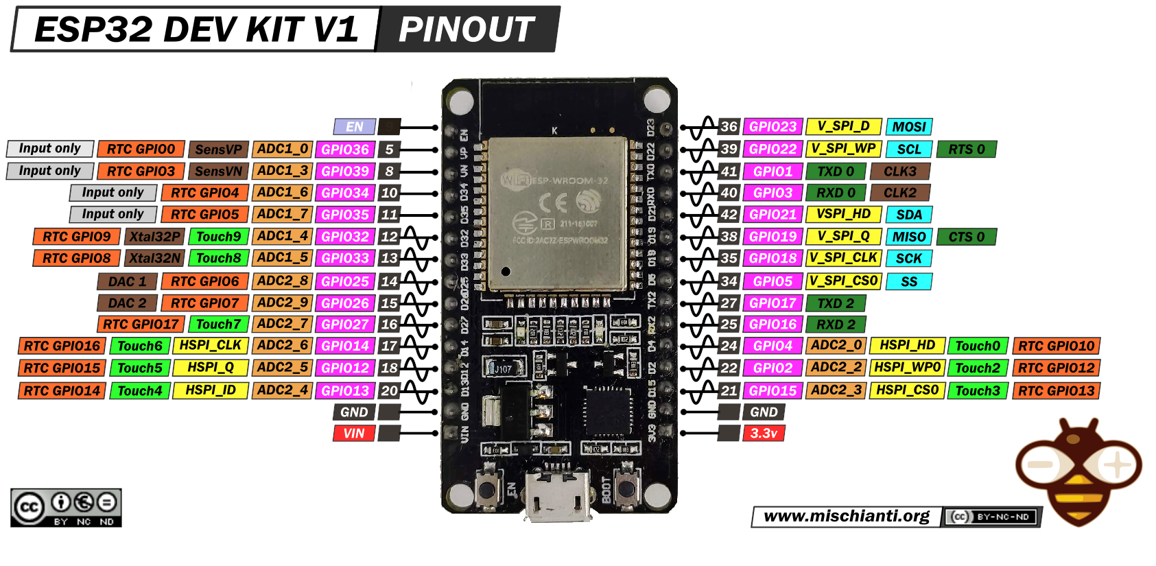
FDC+ RS232 (VCC or 3.3V as required)

RX2 - RXD
TX2 - TXD

SD Card (VCC or 3.3V as required)

D5  - CS
D18 - CLK
D19 - MISO
D23 - MOSI

Head Load LEDs

D27 - Drive 0
D14 - Drive 1
D12 - Drive 2
D13 - Drive 3
Install the Arduino IDE.
In the Board Manager, install esp32 by Espressif Systems and select the DOIT ESP32 DEVKIT 1 board.
Using the Library Manager, install the following libraries:
- ESP Telnet
- SimpleCLI
Download the sketch (firmware source code):
Option 1: Clone the repository with Git (recommended)
Option 2: Download the ZIP file and extract the files into a folder named fdc-sds-esp32.
Use File->Open.. to open fdc-sds-esp32.ino located in the fdc-sds-esp32 folder.
Verify that your ESP32 is connected to your computer with the USB cable. The status is located in the lower right of the Arduino IDE.
Compile and upload the firmware by clicking the right arrow (upload) icon at the top left of the Arduino IDE.
If the upload was successful, the ESP32 will reboot and you will see the D1-D4 LEDs light up during firmware initialization. You should now be able to connect to FDC-SDS-ESP32 command line using a terminal program set to 115,200.
You should now reference the Wiki at the top of this page.