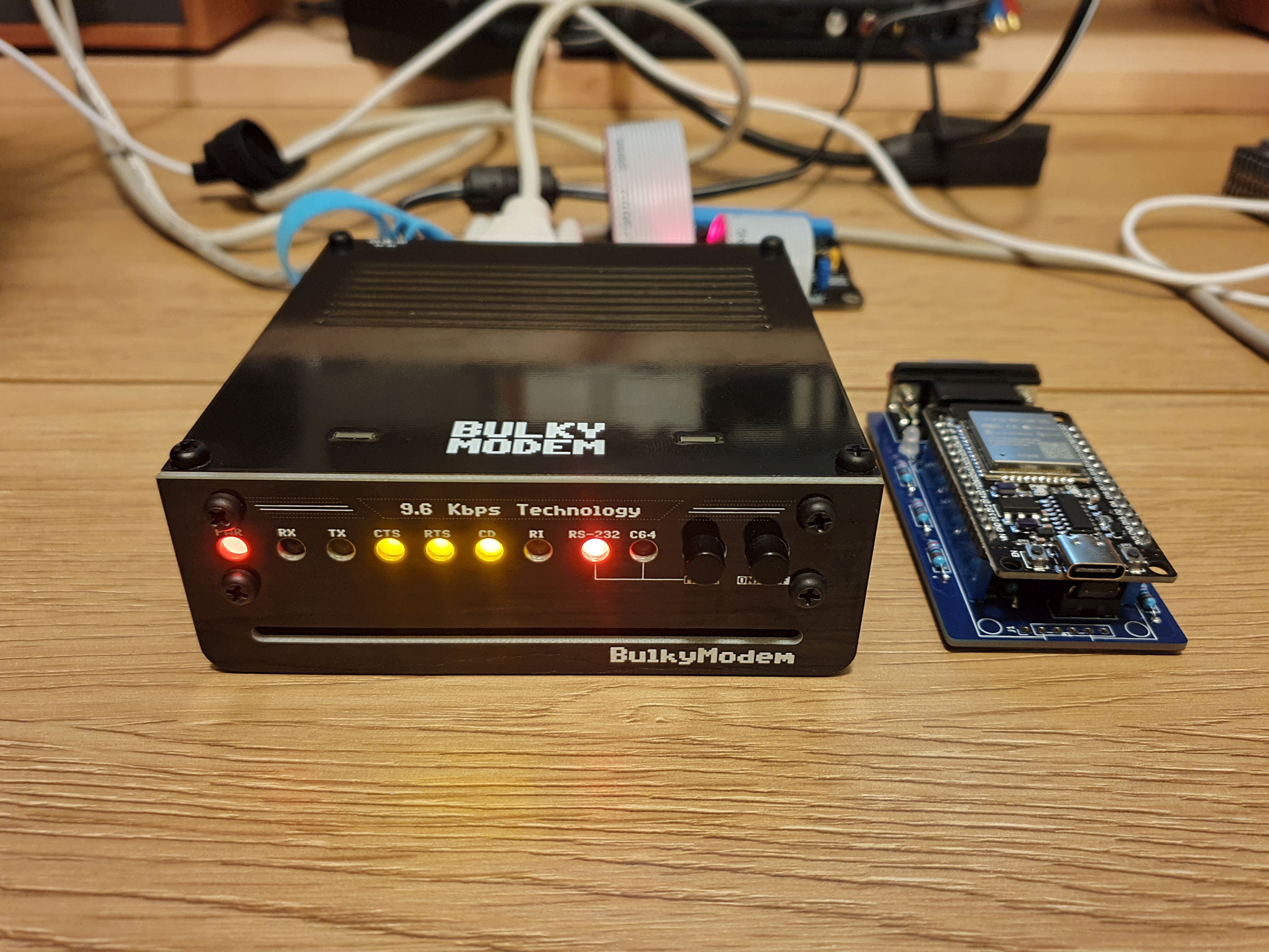
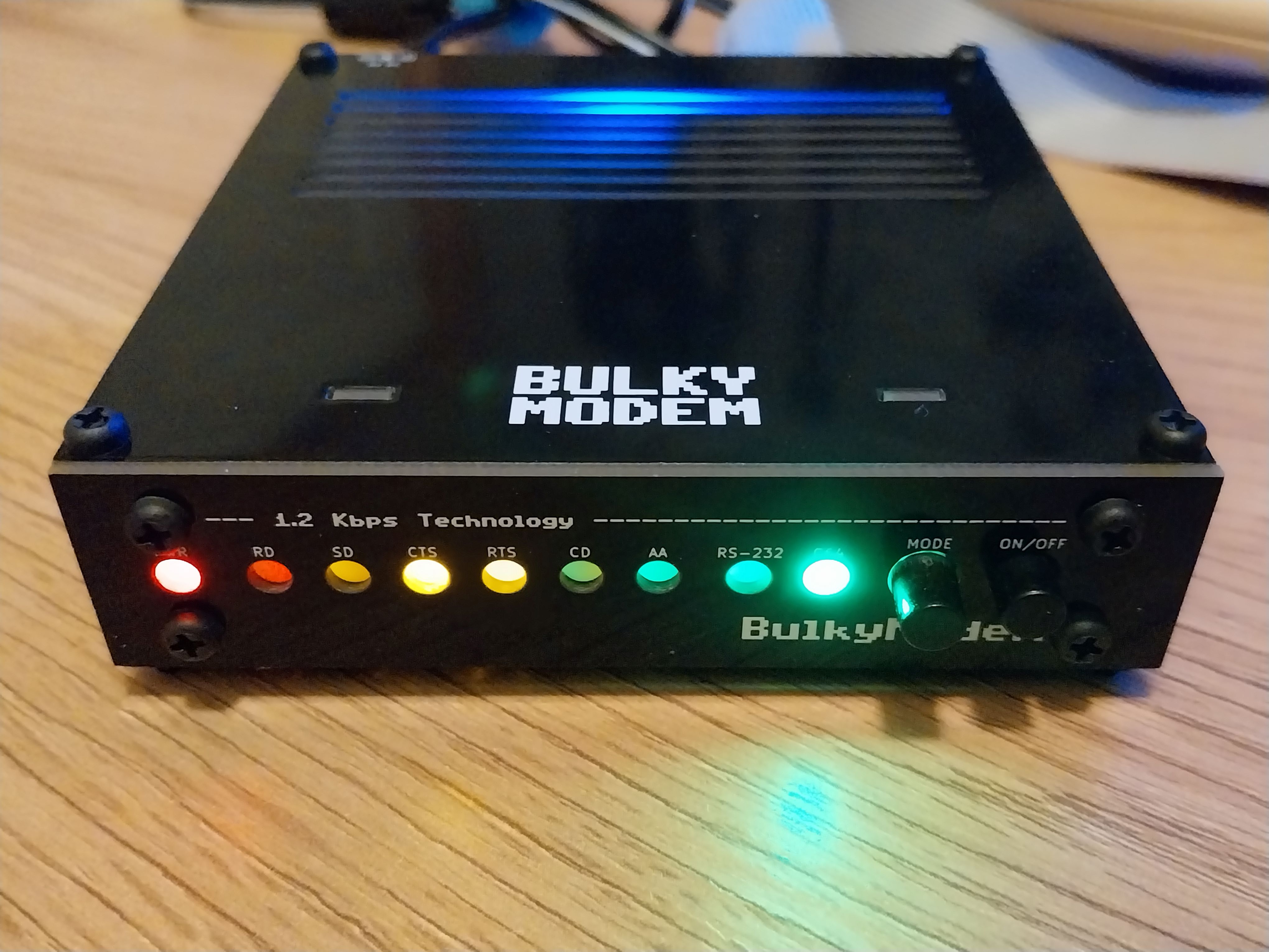
Back in the old days I, like many others, had a modem. Wasn't quite as old that it used an acoustic coupler, but certainly old enough that it still made exciting clicks when connecting up to things. It also made a lot of horrible shrieking noises when it finally got to talk to an actual computer, if someone else was to pick up the phone while you were using it - you'd usually get to hear a bit of swearing before enjoying the task of doing it all over again. The BulkyModem doesn't even hope to do all of those things, but it does allow me to have a go at dialing into a BBS from the comforts of my old PCs again. It doesn't do any of that over an analog phone line, because: A) Those no longer exist, and B) We're living in the far distant future, and we now have Wi-Fi!
While there are many options for modems out there that already do the same thing, even quite cool ones that are still being hand-assembled and sold as Retro WiFi modems in just about every corner of the world. Or, so I assume anyway. The reason being that if you can find a suitably aged nerd tinkering away on their old computer, then they might have been part of the golden age of communication. The other earlier golden age, the one we were talking about before the World Wide Web was unleashed upon the world. Anyway, if you find one of those then there's probably a modem already in their workshop, or possibly in the mail somewhere. So where does my little project fit into all of this? Not sure, but I sure wanted to build one. And the solution I came up with, temporarily fits a very specific spot on my desk.
Where does this one differentiate from the rest of the options then? For that I need to say a bit about my goals when developing it. First off, I wanted to merge old technology with the new - that's not a shocker to anyone who has seen any of my other projects. The second is where this might start becoming of interesting to you, it's the part where I didn't want to build a modem that would only ever work over either RS-232 - or - attached to a Commodore 64/128 User Port. Instead of forcing you to choose, I put a mode-button on the front that rewires things between the two modes. Technically that still requires a choice, but did I mention that it was a button? And it's implemented in hardware!
'That's madness', I clearly hear you shouting at the screen. Possibly scaring a cat while you were doing so. Well, it certainly is!
Which is probably the reason for why I started this project all the way back when these retro modems were still considered a new thing, it just took me a while. Mostly because I couldn't get all of it working at the same time. It was never really supposed to work while connected to two different systems at the same time, that would be a whole different bag of crazy - I just wanted the mode-button to work as previously advertised. And two years later it mostly does. Turns out that juggling chronic fatigue, RS-232 signal names and a screaming toddler at the same time, also means that you're bound to strike out quite a few times. My last stumbling block was that I had one ESP8266 development boards that worked perfectly, and five that mostly did nothing. After three revisions I ended up with five that worked with the addition of a simple diode, it was just that without it - I couldn't get anywhere without figuring out how to actually use an oscilloscope. The twist at the end was that the final board that didn't work at the end, wasn't a twist because the working one just kept working. The sixth was just broken from the start, a fact that seems to align with my batting average for cheap development boards.
As for going all the way in order to not require any changes to the firmware, I later added some optional. Some of those will require an update to the firmware, if I ever get around to making them. We'll well and truly burn that bridge if I ever get around to crossing it, but for now - just pretend that those don't exist! You didn't need them anyway.
For the project background, all of this started with an article: Build your own 9600 Baud C64 WiFi Modem For $10. It goes through all of the steps for building a simple version of this with a specially prepared version of the Zimodem-firmware that was made available when the article was written. For a new project that sounds more outdated than retro, I'm going with the shiny new version instead.
For the technical details as well as information regarding the devices included in this specific GitHub-project, consult the table below to jump to that particular section. Note that in order to successfully use the BulkyModem or BulkyModem-32 along with a Commodore 64, you will also need the User Port-adapter found within the adapters-section.
| Module | Description |
|---|---|
| BulkyModem | BulkyModem-variant based on ESP8266. |
| BulkyModem-32 | BulkyModem-variant based on ESP32. |
| BulkyModem-32 (Mini RS-232) | "Mini"-version of the BulkyModem-32 with an RS-232 interface. |
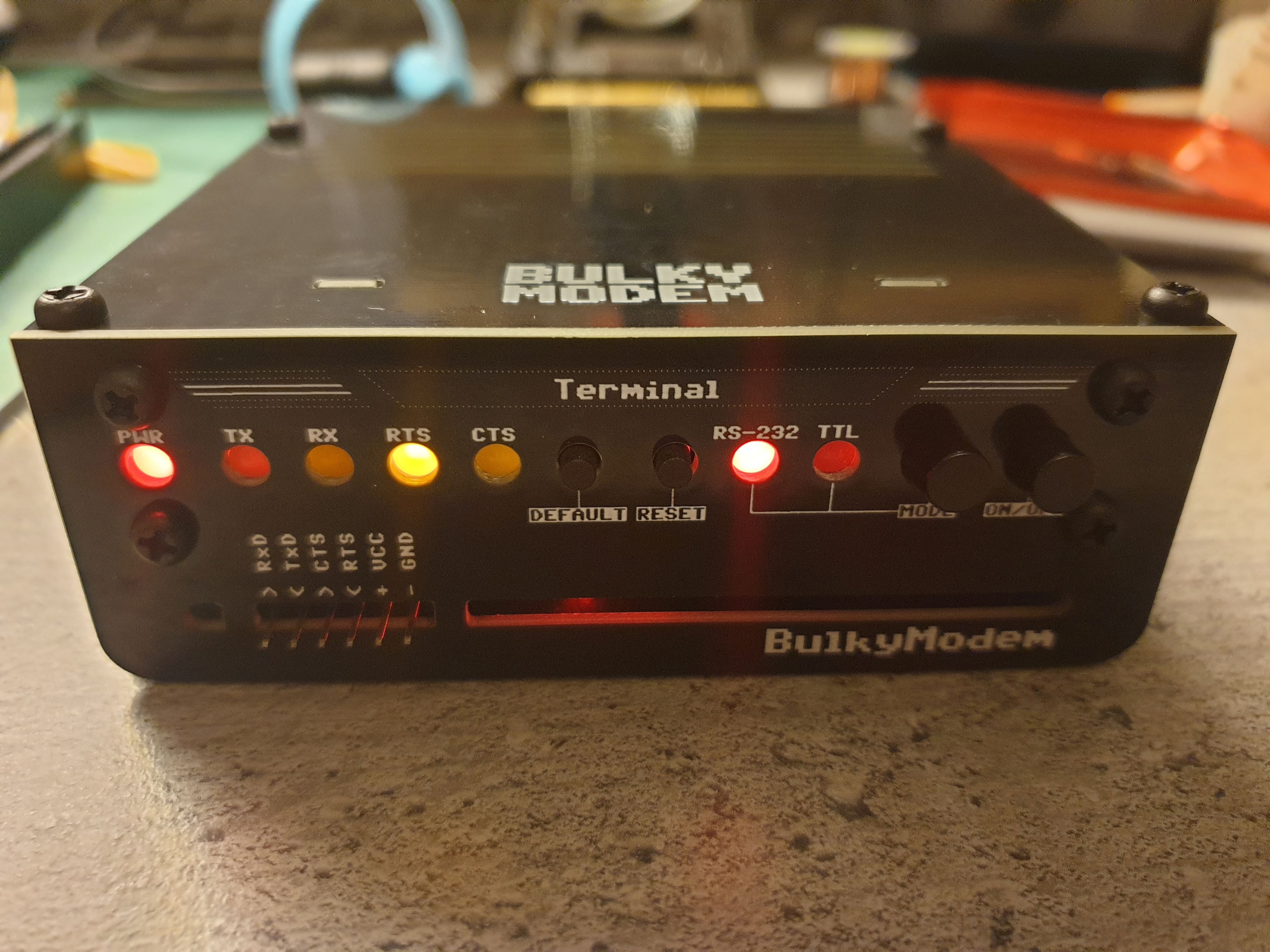
| BulkyModem Terminal | An instant-on video terminal based on VersaTerm |
This is the main module of the project, if you came here looking to build an ESP8266-based retro modem then you've come to the right place. You have the option of going the cheaper route of just building things up on the basic module by itself, consisting only of the main module and nothing else. Alternatively, and this is probably the only reason to build a BulkyModem - and that's to build the whole thing as shown above. Note that the list below will include alternate versions of boards, so you need to decide which of them you'll need based on their description.
| Module | Required | Description | Documentation | Order |
|---|---|---|---|---|
| BulkyModem | Yes | Main module | Documentation, BOM, Setting it up, Getting started | PCBWay |
| BulkyModem Panel | Recommended | Adds a vertical surface for mounting switches and LEDs. | Documentation, BOM | PCBWay |
| 🔂 BulkyModem Panel B | Alternative | Similar to above, but uses an RGB LED as a power indicator. Lights up a different colour when in standby. | Documentation, BOM | PCBWay |
| BulkyModem Front faceplate (FP3) | Recommended | Decorative front panel, mounts on either of the front panels. Has a more futuristic design. | Documentation | PCBWay |
| 🔂 BulkyModem Front faceplate (FP2) | Alternative | Decorative front panel, mounts on either of the front panels. Has a more minimalistic design. | Documentation | PCBWay |
| 🔂 BulkyModem Front faceplate (FP1) | Alternative | Decorative front panel, mounts on either of the front panels. Shorter version (same as shown above). | Documentation | PCBWay |
| BulkyModem Top/bottom faceplate (FA1) | Recommended | Decorative faceplate used on the top of the device, can also be used on the bottom in combination with front faceplate FP2/FP3. | Documentation | PCBWay |
NB! Make sure to follow the links for each of the modules, especially when you're looking into ordering the parts needed to complete the device that you want to build. Those modules are listed with their own link to a BOM, or at least what I would call one. Also keep in mind that to use this with a Commodore 64, you need the User Port-adapter that's found in the adapters-section.
 Status: Working, documentation missing
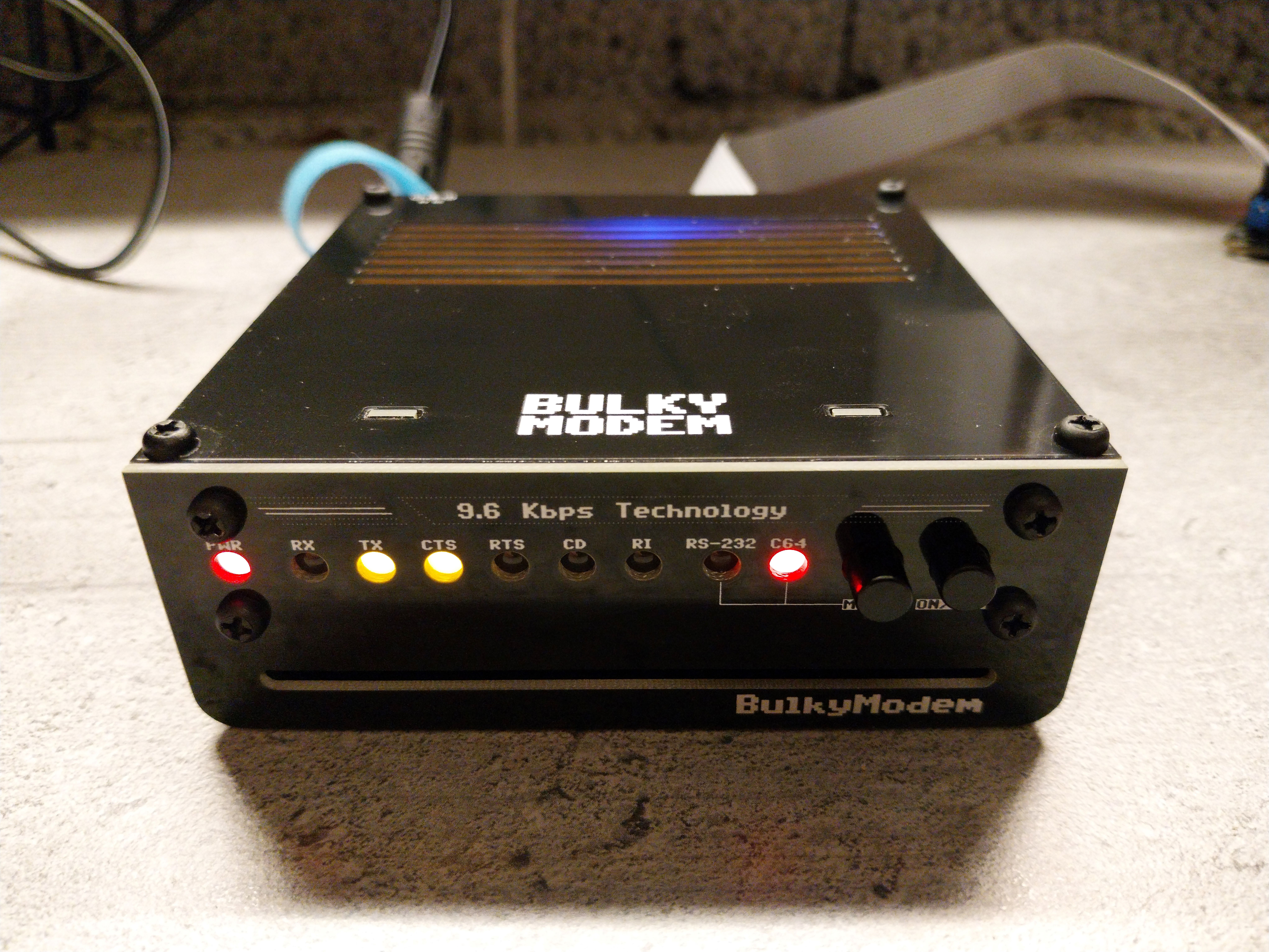
The BulkyModem-32 is a variant of the modem based on the ESP32, offering some additional features when compared to the BulkyModem that was based on the older and more limited ESP8266. More specifically you'll have access to several additional commands and protocols when using this variant, it also includes an SD-card slot so that you can transfer files between the computer and the modem.
For building one of these things you have the option of going the cheaper route of just using the main PCB, leaving you with the main module and nothing else. Alternatively, and this is probably the only reason why you'd want to build a BulkyModem - and that's to go for the whole thing as shown above. Note that there will be alternate versions of some of these boards, so you'll need to decide which of them you want based on their description.
| Module | Required | Description | Documentation | Order |
|---|---|---|---|---|
| BulkyModem-32 | Yes | Main module | Documentation, BOM, Setting it up, Getting started | PCBWay |
| BulkyModem Panel | Recommended | Adds a vertical surface for mounting switches and LEDs. | Documentation, BOM | PCBWay |
| 🔂 BulkyModem Panel B | Alternative | Similar to above, but uses an RGB LED as a power indicator. Lights up a different colour when in standby. | Documentation, BOM | PCBWay |
| BulkyModem Front faceplate (FP3) | Recommended | Decorative front panel, mounts on either of the front panels. Has a more futuristic design. | Documentation | PCBWay |
| 🔂 BulkyModem Front faceplate (FP2) | Alternative | Decorative front panel, mounts on either of the front panels. Has a more minimalistic design. | Documentation | PCBWay |
| BulkyModem Top/bottom faceplate (FB1) | Recommended | Decorative faceplate used on the top of the device, can also be used on the bottom in combination with front faceplate FP2/FP3. | Documentation | PCBWay |
NB! Make sure to follow the links for each of the modules, especially when you're looking into ordering the parts needed to complete the device that you want to build. Those modules are listed with their own link to a BOM, or at least what I would call one. Also keep in mind that to use this with a Commodore 64, you need the User Port-adapter that's found in the adapters-section.
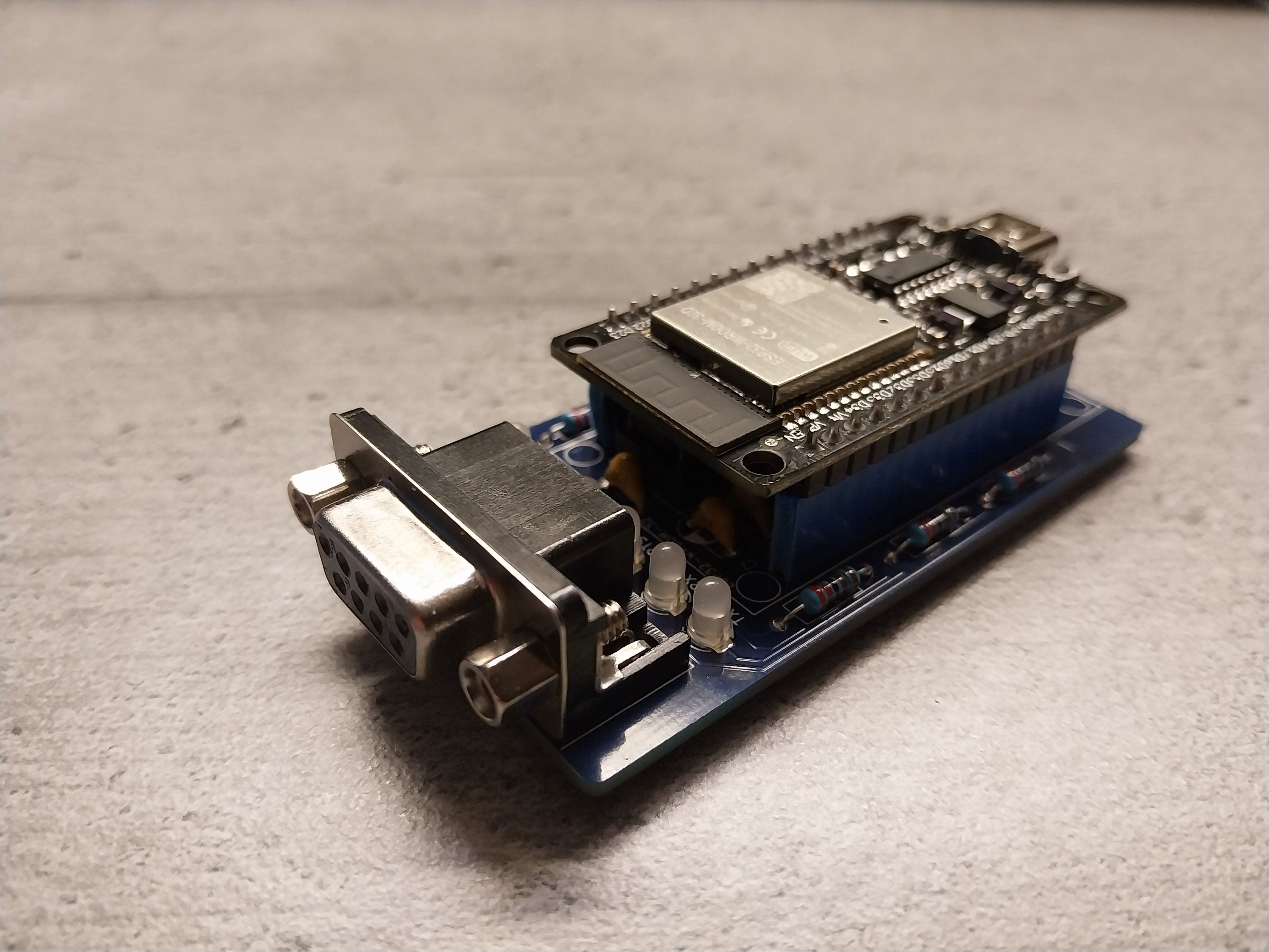
Working on the ESP-32 version of the BulkyModem, that's the one called BulkyModem-32, I had quite a few questions of how some of the features were meant to function. So in order to start development in a more sensible place than what I'm known for, I set out to make a smaller "Mini"-version with the core functionality before trying to add anything else to it. The ESP32-version has more functionality available to it in the Zimodem-firmware, that you'll have available to you when hooking it up to your vintage computers over RS-232. The connection is a 5-wire setup, using RTS/CTS as hardware flow control.
| Module | Required | Description | Documentation | Order |
|---|---|---|---|---|
| BulkyModem-32 (Mini RS-232) | Yes | Main module | Documentation, BOM, Setting it up, Getting started | PCBWay |
 Status: Working, documentation missing
Building a modem comes with its own set of rewards, and in terms of RS-232 these are what we will define as being Data Communications Equipment (DCE). The other end, normally what we would think of as a computer, is instead labelled as Data Terminal Equipment (DTE). With RS-232 we have different wires serving different purposes, so one would have different names on each of these two ends - quite possibly being the reason why this kind of information naturally slides off my brain like water off a duck's back. So naturally I wanted to climb that mountain anyway.
So what does it do then? The idea is that instead of having your homebrew computer such as RC2014, RC6502 and similar living inside a terminal emulator program such as PuTTy or Tera Term on your regular computer, you have something that can do the same except without the distractions of the modern computer. Kind of like the original great devices such as the actual DEC VT101, used to hook up to and talk to early mainframes. For sure, I could have used better examples than what mostly amounts to a bunch of computers hooked up to each other, but I was really looking for something that wasn't just a modem. The point is that you hook up your VGA-monitor, your favorite PS/2 keyboard and then you're free to communicate over serial without notifications, updates and all that. Even if you just put a modem on the end, just so that you could chat on a BBS.
How did I manage to do all this? I didn't. What I did was discover that someone had already made one, they did it with everyone's favorite new microcontroller - Raspberry Pi Pico - and dubbed it VersaTerm. What I did was remove a few features in order to make one that would look really pretty, as well as fit with the overall design of the BulkyModem. If you want the whole thing, check out the original project. You'll need to go there in order to grab the firmware to build mine anyway, so you might as well check it out before deciding.
For the build you have the option of going the cheaper route of just building things up on the basic module by itself, consisting only of the main module and nothing else. Alternatively, and this is probably the only reason to build a BulkyModem Terminal in the first place, and that's to build the whole thing as shown above. There will be alternate versions of some of the board designs, so you need to decide on which one of them you'll need based on their description below.
| Module | Required | Description | Documentation | Order |
|---|---|---|---|---|
| BulkyModem Terminal | Yes | Main module | Documentation, BOM | PCBWay |
| BulkyModem Terminal Panel | Recommended | Adds a vertical surface for mounting switches and LEDs. | Documentation, BOM | PCBWay |
| BulkyModem Terminal Front faceplate (FP3) | Recommended | Decorative front panel, mounts on either of the front panels. Has a more futuristic design. | Documentation | PCBWay |
| BulkyModem Terminal Top/bottom faceplate (FA1) | Recommended | Decorative faceplate used on the top of the device, can also be used on the bottom in combination with front faceplate Terminal FP3. | Documentation | PCBWay |
Separate from the main modules are several adapters, designed for use with the BulkyModem, or BulkyModem-32, in combination with various systems. The repository also includes a folder for schematics in PDF-format, these will be needed in order to track down any faults you encounter when building up and testing any of the adapters.
| Module | Required | Description | Documentation | Order |
|---|---|---|---|---|
| Commodore 64/128 UserPort | Recommended | Used to connect with Commodore 64/128 over the User Port | Documentation, BOM | PCBWay |
NB! The repository may contain pieces of modules and adapters not explicitly listed here, if they're not listed then they're a work in progress. Some might be functional, others might blow up something or I simply haven't remembered to update the documentation.
Everything comes from something, in particular when it comes to most of my electronics projects. I mainly build things I would like to own, often doing a re-spin in order to fit my own preferences for style over function. The hardest parts of the designs will already have been provided for by people more knowledgeable in things, at least at a scale that I can't hope to match. As mentioned in the introduction, all of this was originated in an article - Build your own 9600 Baud C64 WiFi Modem For $10.
The beating heart at the core of almost all of it, is the Zimodem-firmware that runs on an ESP8266/ESP-32. On the C64-side it does have the ability to run at speeds up to 9600 baud which is something that could be met a bit sniggering today, while people at the time would be looking for the butterfly nets. You see, the C64 didn't have an ACIA. There was apparently supposed to be one, but it was removed in order to save on costs. The favored alternative choice then was to attempt to emulate its function, on a computer limited to running at roughly 1 Mhz. In the end your options for modems was the expensive option at 300 baud, followed up by the ridiculously expensive option running at a blistering 1200 baud. The computer actually communicating at 9600 baud in spite of all commonly accepted limitations, is mind-blowing in its execution. For all the details of what ended up being described as UP9600, was initially covered in the article UP9600: How to Bit-Bang 9600 Baud RS-232 on the C64. Even if you don't need all that in order to use it, the article is an interesting feat of engineering. Also, it is one of the only sources that I could find that actually describes how serial on the Commodore 64 actually worked, both now and back then.
