| layout | title |
|---|---|
documentation |
DSA03202 - ZWave |
{% include base.html %}
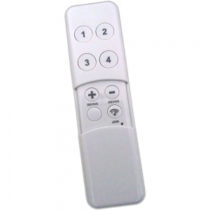
This describes the Z-Wave device DSA03202, manufactured by AEON Labs with the thing type UID of aeon_dsa03202_00_000.
The device is in the category of Remote Control, defining Any portable or hand-held device that controls the status of something, e.g. remote control, keyfob etc..
The DSA03202 does not permanently listen for messages sent from the controller - it will periodically wake up automatically to check if the controller has messages to send, but will sleep most of the time to conserve battery life. Refer to the Wakeup Information section below for further information.
The Minimote is a fully functional Z-Wave remote control capable of adding, removing and controlling other Z-Wave devices. It can also become a secondary or inclusion controller to a SIS gateway in the Z-Wave network. Form-factor, industrial design and robust functionality are the major foci. RF range is 100ft. indoors and 300ft. outdoors.
Network setup buttons (such as adding and removing Z-Wave products to the network) are located underneath the bottom-slide door while Z-Wave scene control buttons are easily available to the user on the top of the remote controller.
By taking advantage of the Z-Wave mesh network, commands can be routed to their destination via intermediary “listening” Z-Wave products. Products that are Z-Wave certified can be used and communicate with other Z-Wave certified devices.
-
Press the button labeled “Learn” – The blue LED will blink slowly.
-
Press the button labeled “Include” on the other Z-Wave controller - The blue and red LEDs will blink quickly to indicate detection of the other Z-Wave controller.
Consult the operation manual of other controllers for instructions on how to add the Minimote as a secondary/inclusion controller into an existing network.
- Consult the operation manual of other controllers for instructions on how to add the Minimote as a secondary/inclusion controller into an existing network.
Once added as a secondary controller, the Minimote cannot be excluded. To remove it from the network, it must be reset.
-
Press and hold both the buttons labeled “Associate” and “Learn” for 10 seconds – The red LED will blink from slow to fast.
-
The blue LEDs will stay solid for 2 seconds to indicate success.
The DSA03202 does not permanently listen for messages sent from the controller - it will periodically wake up automatically to check if the controller has messages to send, but will sleep most of the time to conserve battery life. The wakeup period can be configured in the user interface - it is advisable not to make this too short as it will impact battery life - a reasonable compromise is 1 hour.
The wakeup period does not impact the devices ability to report events or sensor data. The device can be manually woken with a button press on the device as described below - note that triggering a device to send an event is not the same as a wakeup notification, and this will not allow the controller to communicate with the device.
-
Press and hold the button labeled “Learn” for 3 seconds – The Minimote will stay awake for 30 seconds.
-
The blue LEDs will stay solid for 2 seconds to indicate success.
When configuration parameter 250 is enabled, the scene_number channel will have the following values, based on which button is used:
<td>
  <strong>Press</strong>
</td>

<td>
  <strong>Hold</strong>
</td>
<td>
  1
</td>

<td>
  2
</td>
<td>
  3
</td>

<td>
  4
</td>
<td>
  5
</td>

<td>
  6
</td>
<td>
  7
</td>

<td>
  8
</td>
| Physical Button |
| 1 |
| 2 |
| 3 |
| 4 |
The following table summarises the channels available for the DSA03202 -:
| Channel Name | Channel ID | Channel Type | Category | Item Type |
|---|---|---|---|---|
| Scene Number | scene_number | scene_number | Number |
Triggers when a scene button is pressed.
The scene_number channel is of type scene_number and supports the Number item.
The following table provides a summary of the 9 configuration parameters available in the DSA03202. Detailed information on each parameter can be found in the sections below.
| Param | Name | Description |
|---|---|---|
| 241 | Mode of Button 1 (upper left) | Defines the switching mode of Button 1 |
| 242 | Mode of Button 2 (upper right) | Defines the switching mode of Button 2 |
| 243 | Mode of Button 3 (lower left) | Defines the switching mode of Button 3 |
| 244 | Mode of Button 4 (lower right) | Defines the switching mode of Button 4 |
| 245 | Mode of Button 5 (Include) | Defines the switching mode of Button 5 |
| 246 | Mode of Button 6 (Exclude) | Defines the switching mode of Button 6 |
| 247 | Mode of Button 7 (Association) | Defines the switching mode of Button 7 |
| 248 | Mode of Button 8 (Learn) | Defines the switching mode of Button 8 |
| 250 | Secondary Controller Mode | Selects Group Mode or Scene Mode |
| Wakeup Interval | Sets the interval at which the device will accept commands from the controller | |
| Wakeup Node | Sets the node ID of the device to receive the wakeup notifications |
Defines the switching mode of Button 1
The following option values may be configured -:
| Value | Description |
|---|---|
| 0 | Factory Default |
| 1 | Scene Mode |
| 2 | Add Mode |
| 3 | Remove Mode |
| 4 | Association Mode |
| 5 | Learn Mode |
The manufacturer defined default value is 0 (Factory Default).
This parameter has the configuration ID config_241_1_wo and is of type INTEGER.
This is a write only parameter.
Defines the switching mode of Button 2
The following option values may be configured -:
| Value | Description |
|---|---|
| 0 | Factory Default |
| 1 | Scene Mode |
| 2 | Add Mode |
| 3 | Remove Mode |
| 4 | Association Mode |
| 5 | Learn Mode |
The manufacturer defined default value is 0 (Factory Default).
This parameter has the configuration ID config_242_1_wo and is of type INTEGER.
This is a write only parameter.
Defines the switching mode of Button 3
The following option values may be configured -:
| Value | Description |
|---|---|
| 0 | Factory Default |
| 1 | Scene Mode |
| 2 | Add Mode |
| 3 | Remove Mode |
| 4 | Association Mode |
| 5 | Learn Mode |
The manufacturer defined default value is 0 (Factory Default).
This parameter has the configuration ID config_243_1_wo and is of type INTEGER.
This is a write only parameter.
Defines the switching mode of Button 4
The following option values may be configured -:
| Value | Description |
|---|---|
| 0 | Factory Default |
| 1 | Scene Mode |
| 2 | Add Mode |
| 3 | Remove Mode |
| 4 | Association Mode |
| 5 | Learn Mode |
The manufacturer defined default value is 0 (Factory Default).
This parameter has the configuration ID config_244_1_wo and is of type INTEGER.
This is a write only parameter.
Defines the switching mode of Button 5
The following option values may be configured -:
| Value | Description |
|---|---|
| 0 | Factory Default |
| 1 | Scene Mode |
| 2 | Add Mode |
| 3 | Remove Mode |
| 4 | Association Mode |
| 5 | Learn Mode |
The manufacturer defined default value is 0 (Factory Default).
This parameter has the configuration ID config_245_1_wo and is of type INTEGER.
This is a write only parameter.
Defines the switching mode of Button 6
The following option values may be configured -:
| Value | Description |
|---|---|
| 0 | Factory Default |
| 1 | Scene Mode |
| 2 | Add Mode |
| 3 | Remove Mode |
| 4 | Association Mode |
| 5 | Learn Mode |
The manufacturer defined default value is 0 (Factory Default).
This parameter has the configuration ID config_246_1_wo and is of type INTEGER.
This is a write only parameter.
Defines the switching mode of Button 7
The following option values may be configured -:
| Value | Description |
|---|---|
| 0 | Factory Default |
| 1 | Scene Mode |
| 2 | Add Mode |
| 3 | Remove Mode |
| 4 | Association Mode |
| 5 | Learn Mode |
The manufacturer defined default value is 0 (Factory Default).
This parameter has the configuration ID config_247_1_wo and is of type INTEGER.
This is a write only parameter.
Defines the switching mode of Button 8
The following option values may be configured -:
| Value | Description |
|---|---|
| 0 | Factory Default |
| 1 | Scene Mode |
| 2 | Add Mode |
| 3 | Remove Mode |
| 4 | Association Mode |
| 5 | Learn Mode |
The manufacturer defined default value is 0 (Factory Default).
This parameter has the configuration ID config_248_1_wo and is of type INTEGER.
This is a write only parameter.
Selects Group Mode or Scene Mode When in Group Mode, the Minimote is paired directly to devices. When in Scene Mode, Minimote button presses will send SCENE_ACTIVATION commands (NOTE: SCENE_ACTIVATION will only be received if the primary controller is NODE 1). The following option values may be configured -:
| Value | Description |
|---|---|
| 0 | Group Mode |
| 1 | Scene Mode |
The manufacturer defined default value is 0 (Group Mode).
This parameter has the configuration ID config_250_1_wo and is of type INTEGER.
This is a write only parameter.
The wakeup interval sets the period at which the device will listen for messages from the controller. This is required for battery devices that sleep most of the time in order to conserve battery life. The device will wake up at this interval and send a message to the controller to tell it that it can accept messages - after a few seconds, it will go back to sleep if there is no further communications.
This setting is defined in seconds. It is advisable not to set this interval too short or it could impact battery life. A period of 1 hour (3600 seconds) is suitable in most instances.
Note that this setting does not affect the devices ability to send sensor data, or notification events.
This parameter has the configuration ID wakeup_interval and is of type INTEGER.
When sleeping devices wake up, they send a notification to a listening device. Normally, this device is the network controller, and normally the controller will set this automatically to its own address. In the event that the network contains multiple controllers, it may be necessary to configure this to a node that is not the main controller. This is an advanced setting and should not be changed without a full understanding of the impact.
This parameter has the configuration ID wakeup_node and is of type INTEGER.
Association groups allow the device to send unsolicited reports to the controller, or other devices in the network. Using association groups can allow you to eliminate polling, providing instant feedback of a device state change without unnecessary network traffic.
The DSA03202 supports 4 association groups.
Association group 1 supports 5 nodes.
Association group 2 supports 5 nodes.
Association group 3 supports 5 nodes.
Association group 4 supports 5 nodes.
| Command Class | Comment |
|---|---|
| COMMAND_CLASS_NO_OPERATION_V1 | |
| COMMAND_CLASS_BASIC_V1 | |
| COMMAND_CLASS_SCENE_ACTIVATION_V1 | Linked to BASIC |
| COMMAND_CLASS_CONFIGURATION_V1 | |
| COMMAND_CLASS_MANUFACTURER_SPECIFIC_V1 | |
| COMMAND_CLASS_WAKE_UP_V1 | |
| COMMAND_CLASS_ASSOCIATION_V1 | |
| COMMAND_CLASS_VERSION_V1 |
Did you spot an error in the above definition or want to improve the content? You can contribute to the database here.