-
Notifications
You must be signed in to change notification settings - Fork 42
New issue
Have a question about this project? Sign up for a free GitHub account to open an issue and contact its maintainers and the community.
By clicking “Sign up for GitHub”, you agree to our terms of service and privacy statement. We’ll occasionally send you account related emails.
Already on GitHub? Sign in to your account
UART0 RX/TX pins Commit #128
Comments
|
Oops, I have been a bit too quick... The latest commit should work. |
|
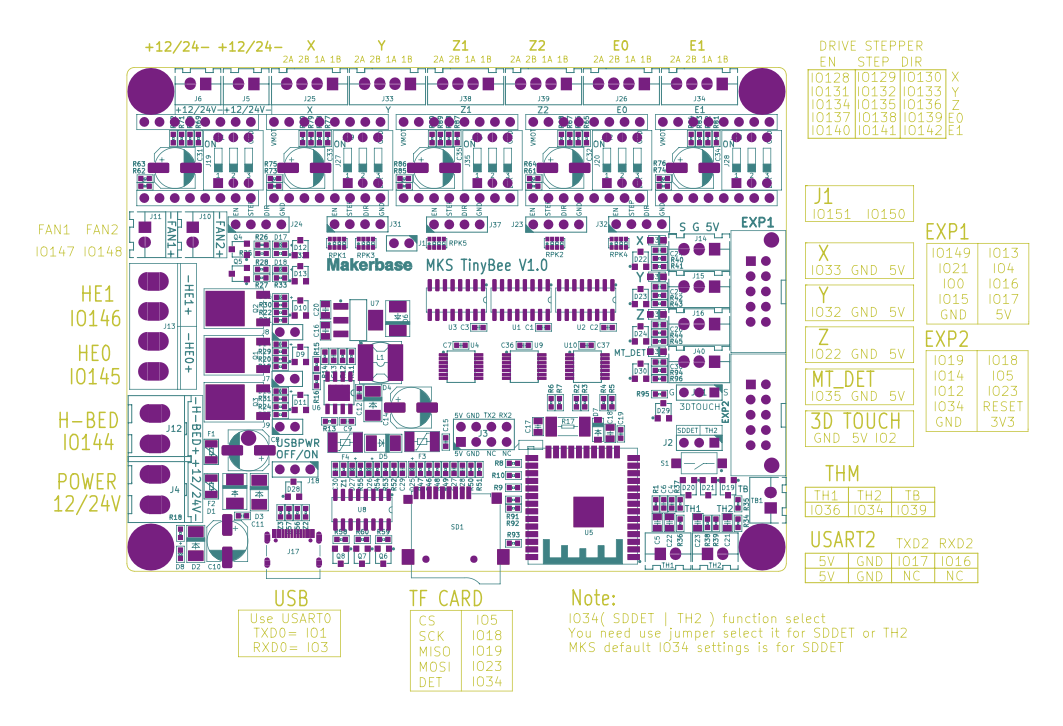
It's still producing the same issue on the TineBee. I have tried even using the pins from UART2 just to make sure my IO were ok to use and it's the same behaviour. #define UART_RX_PIN GPIO_NUM_16 // EXP_1 Anytime uart_set_pin() is run on UART1, the TX is not working |
|
Ah I think I have found the problem. uart->num for Serial 1 is overriding Serial 0 as the case is 1 off (same for others) #ifdef UART0_PINS_REDEFINED |
UART0 -> 34/35 set by the resident guru (serial monitor?) at startup, I do not think it is possible to shut him up completely... And there is something odd going on if remapping UART0 pins, TX data is beeing replicated to pin 35 (by the guru?) I do not know if this is a framework bug or a feature. I do not think it is a grblHAL bug - I would love to set breakpoints to debug this - but there is no (separate?) debug port available... UART2_RX_PIN/UART2_TX_PIN is for UART1, UART1_RX_PIN/UART1_TX_PIN for UART2. Not very logical I know, but due to different MCUs using different numbering schemes. |
|
II'm using IO35 as my auto squater Y axis as it's the same connector as the rest of the end stops. Even if Uart and Y2 limit are on the same pin it seems to work (very strange). I will leave it as is for now. [PIN:34,Feed hold] |

I'm seeing a stange behaviour.
If I set my UART GPIO pins via the new variables, I'm not able to TX via the serial console, If I leave it by default it works fine PIN 34/35.
#define UART_RX_PIN GPIO_NUM_4 // EXP_1
#define UART_TX_PIN GPIO_NUM_13 // EXP_1
If I set my new pins via variables and comment out "uart_set_pin" function:
main/uart_serial.c
#if UART_RX_PIN != 34 || UART_TX_PIN != 35
case 0:
//uart_set_pin(uart->num, UART_TX_PIN, UART_RX_PIN, UART_PIN_NO_CHANGE, UART_PIN_NO_CHANGE);
break;
#endif
It also works fine and I'm able to RX and TX:
MSG:WIFI AP SCAN COMPLETED]
[PIN:34,Feed hold]
[PIN:36,Cycle start]
[PIN:39,Probe]
[PIN:33,X limit min]
[PIN:32,Y limit min]
[PIN:35,Y limit min 2]
[PIN:22,Z limit min]
[PIN:12,Aux in 0,P0]
[PIN:I2S1,X step]
[PIN:I2S4,Y step]
[PIN:I2S10,Y2 step]
[PIN:I2S7,Z step]
[PIN:I2S2,X dir]
[PIN:I2S5,Y dir]
[PIN:I2S11,Y2 dir]
[PIN:I2S8,Z dir]
[PIN:I2S0,X enable]
[PIN:I2S3,Y enable]
[PIN:I2S9,Y enable]
[PIN:I2S6,Z enable]
[PIN:I2S17,Spindle on]
[PIN:I2S18,Spindle direction]
[PIN:2,Spindle PWM]
[PIN:I2S20,Mist]
[PIN:I2S19,Flood]
[PIN:19,MISO]
[PIN:23,MOSI]
[PIN:18,SPI CLK]
[PIN:5,SD card CS]
[PIN:4,RX,Primary UART]
[PIN:13,TX,Primary UART]
[PIN:16,RX,Modbus]
[PIN:17,TX,Modbus]
The text was updated successfully, but these errors were encountered: